This document replaces an earlier version called 'UNIFACE and the N-Tier Architecture'
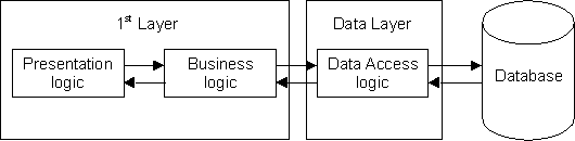
The most common method of developing a client/server system in UNIFACE is to use the traditional 2-Tier structure. This consists of a primary tier (or layer) which incorporates all presentation and business logic, and a secondary tier (or layer) which contains all data access logic. This can be represented in the following diagram:
Figure 1 - The 2-Tier Structure
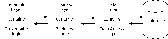
For those of you who are unfamiliar with this terminology, which appears to change whenever a new methodology becomes fashionable, here is a translation table:
The Presentation/Business Layer is provided by UNIFACE form components, perhaps coupled with report and service components, which contain the code that was developed for the particular application.
The Data Layer is provided by the various database drivers which allow the UNIFACE application to communicate with any of the most common DBMS systems which are available today. The physical database can be switched from one vendor's product to another simply by making a change in the assignment file, and not by changing any code within the application.
The disadvantage of this structure is that several components may deal with the same business entity (or object) but differ only in the way that the data is presented. This therefore implies that these components contain their own copies of the same business logic, which results in the need to change the code in each and every copy whenever the business rules change.
The components in the primary layer of this type of structure are heavy and bloated with code, and have thus been given the name 'Fat Client'.
This splits each of the three logical areas into its own layer. For this structure to work effectively there should be clearly defined interfaces between each of the layers. This should then enable components in one layer to be modified without requiring any changes to components in other layers. One example is changing the file system from one DBMS to another, or changing the user interface from one system to another (e.g. from client/server to the web).
The main advantage of this structure over the 2-Tier system is that all business logic can be defined once within the business layer and then shared by any number of components within the presentation layer. Any changes to business rules can therefore be made in one place and be instantly available throughout the whole application. This structure can be implemented in UNIFACE as follows:
Figure 2 - The 3-Tier Structure
The components in the primary layer of this type of structure have much less code, and have thus been given the name 'Thin Client'.
With version 7.2.04 of UNIFACE Compuware sought to aid the development of a 3-tier structure with the introduction of a new type of service component called an Object Service. A superior solution (in my opinion) has been made available in version 7.2.06 with the introduction of XML streams. First let us examine their characteristics:
This can be represented in the following diagram:
Figure 3 - Object Services in action
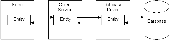
Note that with the exception of one-to-many pairs each entity will require its own object service.
retrieve and store operations must be replaced with xmlload and xmlsave using an XML stream which is handled by a service component that deals with that DTD. From my own experience conversion can be made considerably easier by using component templates (refer to my article 'The Power of Component Templates' for more details).This can be represented in the following diagram:
Figure 4 - Using XML Streams
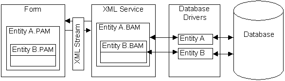
Note that the entire contents of a form can be handled with a single XML stream and therefore a single XML Session Service. It is possible to use different streams for such things as foreign entities, and each different stream will require its own service component.
retrieve to populate its structure with all the required entities and occurrences, followed by an xmlsave to construct the XML stream, which is then passed back to the form component.xmlload statement.store - instead the form does an xmlsave to construct a new XML stream, then passes that stream to the Session Service.xmlload to populate its structure using the latest data, followed by a retrieve/reconnect to re-attach each occurrence to the database. This automatically identifies existing occurrences which are to be updated or deleted, or new occurrences which are to be added. Provided that all validation is performed successfully this is followed by a store and commit.Because the form component does not obtain its data directly from, nor write its changes directly to the physical database, it deals with what are known as disconnected record sets. It obtains its data from an XML stream, and writes its changes to an XML stream. It is the responsibility of the Session Service to read from and write to the physical database (either directly or via Object/Entity Services).
The use of XML streams therefore moves all data access and business logic from the form component (presentation layer) to the session service component (business layer). It also means that components in the presentation layer can be more easily replaced with components written in a language other than UNIFACE. Any language that can deal with XML streams can be used. This is far easier than trying to find one that can deal with the ENTITY or OCCURRENCE parameter, or lists with the <GOLD>semi-colon separator.
Note that there is no allowance for stepped hitlists with the xmlsave statement - it will retrieve ALL available occurrences into a single XML stream. It is possible to prevent a full table scan on large tables by restricting the number of occurrences with the maxhits option in the read statement.
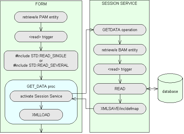
The method by which a presentation layer component obtains data via an XML stream can be illustrated in a process flow diagram as shown in figure 5. Note that this involves a change to the contents of the <read> trigger.
Figure 5 - obtaining data via an XML stream
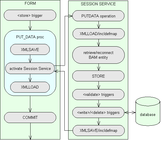
The method by which a presentation layer component stores data via an XML stream can be illustrated in a process flow diagram as shown in figure 6. Note that this involves a change to the contents of the <store> trigger.
Figure 6 - storing data via an XML stream
These diagrams are explained in more detail in my 3 Tier Development Guidelines which were produced following the conversion of my entire sample application and Menu/Security system from 2-tier to 3-tier.
During my investigations I came across the following 'features' which were not covered in the documentation:
xmlsave command will cause the <READ> trigger to be fired on all necessary occurrences it will not fetch them into the structure and the XML stream will contain null values. To force the data to be fetched you can either paint one of the fields, or reference one in proc code after the read statement.By this I mean having one model for the business/data layers (Business Application Model or BAM) and a separate model for the presentation layer (Presentation Application Model or PAM).
'Why should you want two different models?' I hear you ask. The reason is simple - the way that the data is held in the physical database (BAM) may be rather different from how it needs to be presented to the user. Data may have to be obtained from several entities which are joined in complex relationships, or constructed at run time using the contents of other fields. The presentation model (PAM) can therefore be a simplified version of the business model (BAM), and can hide the complexities of the physical database.
This arrangement also allows for the possibility that the physical database could be altered without requiring corresponding changes to large numbers of components - such changes could be limited to components in the business layer and not the presentation layer.
Readers may be aware that in May of this year I wrote an article entitled 'A separate Application Model for Presentation Layer'. This documented an attempt to provide this facility by making alterations to object services. It worked, but was far from perfect. I have now rebuilt that entire set of sample code using XML streams, and I have to say that the result is far more satisfactory and more suitable for use in a production environment.
This is the application model which is referenced by all components in the Business and Data layers. It has the structure shown in figure 7:
Figure 7 - The XAMPLE database

Each PERSON may have one or more addresses (PERS_ADDR) over a period of time, each with its own start and end dates. Each address has its own set of address lines (PERS_ADDR_LN), with blank lines not being stored in the database.
There are numerous OPTIONS available, but each one can be turned on or off for each PERSON. Options which are turned on for a person have records written to PERS_OPT_XREF.
This is the application model which is referenced by all components in the Presentation Layer. It has the structure shown in figure 8:
Figure 8 - The USER database

At first glance the XAMPLE and USER models look similar, but there are differences:
You may notice that I have changed the prefix on each entity name between the two models. This was done just to ensure that the DTD mapping feature actually worked (it's not that I don't trust Compuware's code, but ………). In a production environment it is quite likely I would not change the entity names between the two models.
The ability to add fields to an entity which are constructed at run time by the service component is an extremely useful one. For example, descriptions from foreign entities can be added, such as PERS_TYPE_DESC and NODE_DESC to Z_PERSON, thus removing the need to paint those foreign entities in the form component when it is required to display those descriptions. Other fields may require more complicated code for their construction, such as ADDRESS_TEXT, but this is all transparent to the form component.
Before I go any further let me identify some silly ideas proposed by some former colleagues:
Firstly, it has been said that because the elements that are referenced by the presentation layer do not come directly from the physical database that it is not necessary to define them in any application model - they can simply be defined as dummy entities and dummy fields in individual components as and when required. This attitude shows a total lack of understanding about the use of a repository-based language such as UNIFACE. The whole idea of a repository is that objects can be defined once and used many times over. Anyone who says that when you want to use an object you must type out its details in longhand instead of merely picking it out of a central repository does not have a place in today's world of software engineering and should take up a profession that is more suited to their talents, such as pig farming or road sweeping.
Secondly, having accepted that the elements referenced by the presentation layer should be defined in an application model, it has then been said that because they do not reside in the physical database that all entities and fields should be marked as 'non-database' and that no keys or relationships need be defined. I have worked briefly in such an environment, and as far as I am concerned such ideas are complete rubbish. In my USER model all entities and fields are defined as 'in database' for the following reasons:
$keyfields function and putlistitems/id command to extract the primary key values from an occurrence for passing as a parameter to a child component. This cannot work if the key is not defined, nor will it work successfully if the key fields are defined as 'non-database'.$selectlist function so that each form component can supply the session service with a list of those fields which it actually requires. This means that any constructed fields that are not required do not have to be constructed, thus do not waste any processing effort.As you can see my reasons for defining the entities and fields in the presentation model as 'in database' are entirely practical, not ideological. I deal in methods that work, not theories that don't.
Now let me identify the form components in my sample code that are used to present this data to the user:
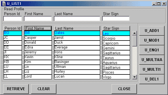
This lists occurrences of PERSON, and has buttons which pass control to other forms.
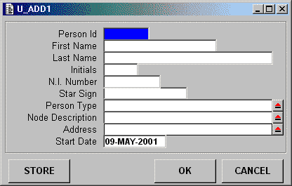
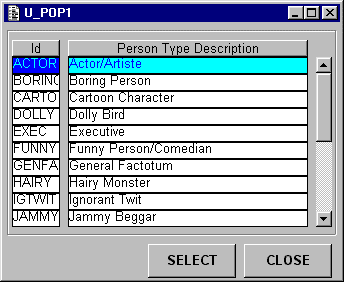
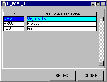
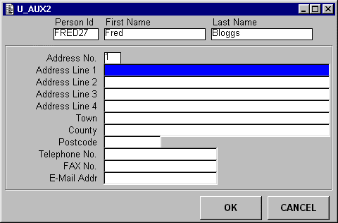
This adds a new occurrence of PERSON to the database. Values for PERSON TYPE are picked from U_POP1. Values for NODE are picked from U_TREE_POP1 and U_POP1_4. Details for the first address are entered via screen U_AUX2.
This lists all available occurrences of PERSON TYPE and allows the user to pick one.
This lists the contents of a structure hierarchy and allows the user to pick one. The tree type is chosen using form U_POP1_4.
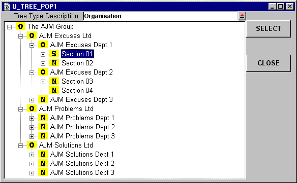
This shows all available occurrences of TREE TYPE and allows the user to pick one.
This allows the details for a PERSON's first ADDRESS to be entered.
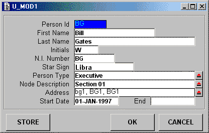
This shows the existing details for a PERSON and allows the user to change them. Values for PERSON TYPE are picked from U_POP1. Values for NODE are picked from U_TREE_POP1 and U_POP1_4. The address can be changed via screen U_MOD1_2.
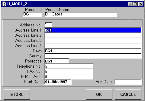
This shows the existing details for a PERSON's address and allows the user to change them.
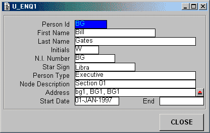
This shows the existing details for a PERSON, but does not allow changes to be made. The full address details can be examined using screen U_AUX1.
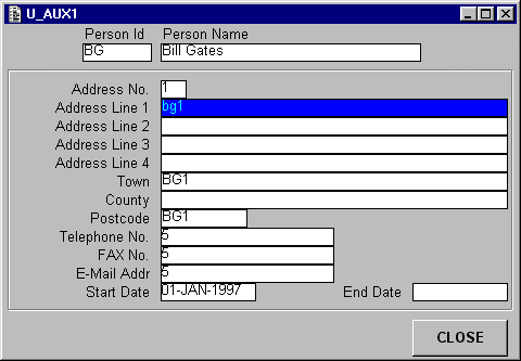
This will display the full details of a PERSON's ADDRESS.
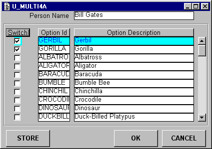
For the selected PERSON this will list all occurrences of OPTION and show whether each OPTION has been switched ON or OFF by means of a checkbox. The value of each checkbox can be modified directly, or the user can double-click anywhere on the line.
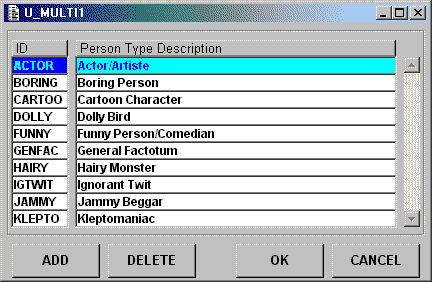
This will allow occurrences of PERSON_TYPE to be added, modified or deleted.
| DTD Name | Comments |
|---|---|
| Z_PERSON | Contains entity Z_PERSON. Used in form U_ADD1, U_DEL1, U_ENQ1, U_LIST1, U_MOD1 |
| Z_PERS_ADDR | Contains entity Z_PERS_ADDR. Used in form U_ADD1, U_AUX1, U_AUX2, U_MOD1_2 |
| Z_PERS_OPT_XREF | Contains entity Z_PERS_OPT_XREF and Z_PERSON. Used in form U_MULTI4A |
| Z_PERS_TYPE | Contains entity Z_PERS_TYPE. Used in form U_POP1, U_ADD1, U_MOD1 |
| Z_TREE_NODE | Contains entity Z_TREE_NODE. Used in form U_TREE_POP1, U_ADD1, U_MOD1 |
| Z_TREE_TYPE | Contains entity Z_TREE_TYPE. Used in form U_POP1_4, U_TREE_POP1 |
As you can see from this list it is possible to use the same DTD in more than one component. For example, Z_PERSON is used in form U_LIST1 to select and retrieve multiple occurrences, whereas the others deal with adding, deleting, displaying or modifying a single occurrence at a time.
It is also possible to use more than one DTD in the same form. For example, form U_ADD1 uses Z_PERSON to create the person details, and Z_PERS_ADDR to create the first address. Forms U_ADD1 and U_MOD1 also make use of the DTD's for Z_PERS_TYPE and Z_TREE_NODE to populate the foreign entities with new selections.
Z_PERS_OPT_XREF is constructed from two entities. It takes all the occurrences of X_OPTION then sets a checkbox on if a corresponding occurrence exists on X_PERS_OPT_XREF. When the xmlstream is returned for updating, occurrences of X_PERS_OPT_XREF are either created or deleted, depending on the value of this checkbox.
Because my form components and DTDs both reference entities from the USER model (PAM) no mapping parameters are required for manipulating XML streams in these components. Mapping is required in each of my session service components as they reference entities only from the XAMPLE model (BAM). Default mapping is defined using the DTD editor that is built into the UNIFACE IDE, therefore there is no need to specify any manual mapping.
Creating a component template for the Session Services was a relatively simple procedure. I eventually ended up with the following operations:
GETDATA(profile, selectlist, orderby, options, xmlstream)
This is used instead of the read operation in the <read> trigger. By replacing the code in the <read> trigger I am still able to use the retrieve command.
PUTDATA(xmlstream)
valerr attribute.This is used instead of a store.
VALIDATE(xmlstream, fieldname, changes)
This can be activated from the <validate occ> or <validate field> triggers in form components to give the same frequency of validation as is found in a 2-tier system. The stream is returned to the form in case any values are changed during the validation process, or if any error messages have been inserted into the valerr attribute of any field or occurrence by means of the $fieldproperties or $occproperties functions.
VALIDATEKEY(xmlstream, keynumber)
$curkey).This can be activated from the <validate key> trigger in form components to give the same frequency of validation as is found in a 2-tier system.
VERIFY_DELETE(xmlstream)
UCOMMIT() or UROLLBACK()
commit or rollback is issued in a presentation layer component because it detects that an object service has been defined in the entity's properties.My experiments have proved (to me at least) that the introduction of XML streams into UNIFACE provides a great step forward in the support of a 3-tier architecture. It is certainly more flexible than what had been offered earlier with object services. The ability to allow the presentation layer to use its own application model, a simplified version of the one used by the business layer, is an added feature that some may not know how to exploit. This article is my attempt to demonstrate how XML streams can be used in a 3-tier architecture and what benefits they can provide.
The software used in my experiments is available for download here from my web site so that you can check the results for yourself. Please feel free to play with it. Any comments would be most welcome.
Be aware that my sample code will not run perfectly unless you are running 7.2.06 with Service Pack 1 and Patch W640. There are some minor problems outstanding (see the following table), but these are not serious.
The problems I have reported to Compuware are as follows:
| Log/SPR/BUG# | Description | Fixed? |
|---|---|---|
| Bug 23469 | Never-ending loop after xmlload and retrieve/reconnect when using putlistitems/occ | Patch W640 |
| Bug 23469 | Never-ending loop after retrieve/reconnect | Patch W640 |
| Log 27348 | Retrieve/reconnect loses data on an 'up' entity | Patch W640 |
| Bug 23470 | Change to foreign key value is lost with xmlload | Patch W640 |
| Bug 23433 | VALIDATE command does not return -1 if associated validation returns -1 | Service Pack 1 |
| Bug 22735 | Unable to map fields correctly in DTD | Service Pack 1 |
| Bug 23469 | Non-database fields being corrupted after xmlload and retrieve/reconnect. | Patch W640 |
| Log 29917 | XMLSAVE will abort in YRTLC.DLL if form contains fewer fields than are defined in the DTD (workaround is to set fieldlist to 'ALL'). | Patch W672 |
| Log 29938 | RETRIEVE/RECONNECT is not detecting a duplicate key if $occstatus='new' and a record with the same primary key already exists (and a field is modified by the contents of the <format>/<deformat> trigger). | |
| Log 29942 | The <QUIT> trigger in a form component will not fire if that form has child components which are services (but not object services). | Fixed by removing code from the <QUIT> trigger in the service. |
| BUG 24107 | $fieldproperties will not work if attempting remote validation in a self-contained service. | |
| SPR 50203 | Field validation trigger fired because of <store> causes error in YRTLC.DLL when it reaches the DONE statement. | Cannot use DISCARD in this trigger - see Call Log 31158 |
| Log 30173 | XMLSAVE is not picking up value for 'errormsg' set by $occproperties or $fieldproperties when performing remote validation. | |
| Log 30842 | Performing a DISCARD after an XMLLOAD in the <validate field> trigger causes a page fault. | Cannot use DISCARD in this trigger - see Call Log 31158 |
| Log 30875 | XMLLOAD will sometimes change $occstatus from 'est' to '', thus causing an existing occurrence to be treated as a new one and rejecting the primary key as a duplicate. | |
| Log 30949 | XMLLOAD will create corrupt occurrences if the DTD contains a field with the same name as the entity. | |
| Log 31157 SPR 50394 |
An '/init' switch is needed on XMLLOAD so that no field or occurrence modification flags are set after data is loaded into the component. | |
| Log 31158 SPR 50395 |
A '/replace' switch is needed on XMLLOAD so that existing occurrences in the component are replaced rather than new occurrences appended. | |
| Log 31198 | Remote validation not supported in field or occurrence triggers of client/server forms. | Linked to Call Log 31157 and 31158 |
| SPR 50504 BUG 24394 |
Occurrence which is created then deleted is being included in the XML stream which is passed to the session service. This tries to delete an occurrence which does not exist. | Service Pack 3 Patch Z036 |
Tony Marston
23rd September, 2000
mailto:tony@tonymarston.net
mailto:TonyMarston@hotmail.com
http://www.tonymarston.net
| 14th August 2002 | Updated list of outstanding bugs for Patch Z036.
Re-issued sample code. |
| 27th June 2002 | Added diagrams to illustrate how a presentation layer component can obtain and store data via an XML stream. |
| 23rd May 2002 | Updated procs in line with the 3 Tier version of my demonstration application.
Re-issued sample code. |
| 29th March 2002 | Removed the profile and options arguments from the VERIFY_DELETE operation.
Streamlined code following experiences gained while converting my entire demonstration application to 3 Tier. Re-issued sample code. |
| 28th Sept 2001 | Added changes argument to VALIDATE operation to circumvent the problem caused by remote validation not being supported from a field or occurrence trigger. I now perform getlistitems instead of xmlload and return error messages via the Message Object described in my article Error/Message Handling for self-contained services.
Re-issued sample code. |
| 21st Sept 2001 | Removed selectlist argument from PUTDATA and VALIDATE operations.
Re-issued sample code. |
| 17th Sept 2001 | Added component U_MULTI1. Modified sample code so that session services include both the BAM and the PAM entities to allow for the translation of item names in retrieve profiles should they be different between the two models. |
| 3rd June 2001 | Updated sample code to deal with situation where a record being amended by one user is amended or deleted by another user. |
| 26th May 2001 | Renamed the UI model to the PAM (Presentation Application Model).
Renamed the physical model to the BAM (Business Application Model). Added operations UCOMMIT and UROLLBACK to session service components. Re-issued sample code. |
| 9th May 2001 | Removed section 5.f DELDATA as this can be done by PUTDATA.
Added candidate key NAT_INS_NO to the PERSON entity to test key validation. Re-issued sample code. |
| 26th April 2001 | Added section 5.d VALIDATEKEY to get around problem with retrieve/reconnect and $occstatus='new'.
Re-issued sample code. |